
Thin Lenses: Everything About Their Properties and Calculations
Summary:
This class introduces thin lenses, explaining their types (convergent and divergent), their optical properties, and the object-image relationship. Graphical methods are presented, and the lens maker’s equation is derived to understand their functioning. The aim is to provide a basic understanding of thin lenses and their application in optics, complemented with practical exercises.
Learning Objectives:
By the end of this class, the student will be able to:
- Understand the optical properties of thin lenses, including focal length and focal points.
- Identify different types of thin lenses, such as convergent and divergent lenses, and their applications.
- Apply the object-image relationship to solve optical problems using thin lenses.
- Analyze how spherical surfaces in thin lenses affect light refraction.
- Explain the lens maker’s equation and its relevance in the manufacturing of optical lenses.
- Use graphical methods to determine the positions of image and object in thin lenses.
- Calculate the magnification of images produced by thin lenses.
- Deduce formulas from the geometry of thin lenses to solve optical problems.
TABLE OF CONTENTS
Introduction
Types of Lenses
Properties of Thin Lenses
Lens Maker’s Equation
Graphical Methods for Thin Lenses
Exercises
Introduction
Thin lenses, along with mirrors, are by far the most widely used optical devices. These are transparent objects whose surface is bounded by two spherical interfaces and are generally made of glass or plastic.

In a thin lens, the distance between the refractive surfaces is small enough to be considered negligible.
Types of Lenses
Lenses, like mirrors, are divided into two types: convergent and divergent.
 Thin Convergent Lens
 Thin Divergent Lens
The points F_1 and F_2 are the focal points, and f is the focal length. In a thin lens, the two focal lengths are equal, so they are represented by the same letter.
In a thin lens, the distance between the refractive surfaces is small enough to be considered negligible.
Properties of Thin Lenses
If we do geometry with a convergent lens, we will see the following:

Since the painted triangles are similar, the corresponding sides will be proportional
\begin{array}{rlr} &\displaystyle \frac{y}{s} = -\frac{y^\prime}{s^\prime} & \\ \\ \equiv & \displaystyle \color{blue}{\frac{y^\prime}{y} = -\frac{s^\prime}{s}} & (\triangle) \end{array}
Similarly,
\begin{array}{rlr} & \displaystyle \frac{y}{f} = -\frac{y^\prime}{s^\prime-f} & \\ \\ \equiv & \displaystyle \color{blue}{\frac{y^\prime}{y} = -\frac{s^\prime-f}{f}} & (\star) \end{array}
Then, from (\triangle) and (\star) we have:
\begin{array}{rlr} &\displaystyle-\frac{s^\prime}{s} = -\frac{s^\prime-f}{f} & \\ \\ \equiv \displaystyle & \frac{s^\prime}{s} = \frac{s^\prime-f}{f} = \frac{s^\prime}{f} - 1 = \frac{s^\prime}{f} - \frac{s^\prime}{s^\prime} & \\ \\ {} \equiv & \displaystyle \frac{s^\prime}{s}+ \frac{s^\prime}{s^\prime} = \frac{s^\prime}{f} & \\ \\ \equiv & \displaystyle \color{blue}{\frac{1}{s}+ \frac{1}{s^\prime} = \frac{1}{f}} & \end{array}
The above is what we call the object-image relationship for thin lenses.
magnification factor m through
\displaystyle \color{blue}{m=-\frac{y^\prime}{y}= - \frac{s^\prime}{s}}
Lens Maker’s Equation
A thin lens, as we know, is composed of two spherical interfaces that separate mediums through which light travels, and we have already studied what happens when light crosses from one medium to another across interfaces of this style. Therefore, to analyze thin lenses, we will suffice to compose what we have already reviewed for individual interfaces.
In general, a thin lens has the following appearance:

But for simplicity, this can be separated

Since we have already analyzed each case (here), we can extract the following two equations:
For side a-b:
\displaystyle \frac{n_a}{s_a} + \frac{n_b}{s_{ab}^\prime} = \frac{n_b - n_a}{R_c}
For side b-c:
\displaystyle \frac{n_b}{s_{b}} + \frac{n_c}{s_{bc}^\prime} = \frac{n_c - n_b}{R_a}
At this point, if we set n_a = n_c = n_{air}\approx 1.0, it will occur that s_b = -s_{ab}^\prime; therefore, these equations are written as follows
\begin{array}{rl} \displaystyle \frac{1}{s_a} + \frac{n_b}{s_{ab}^\prime} & \displaystyle = \frac{n_b - 1}{R_c} \\ \\ \displaystyle -\frac{n_b}{s_{ab}^\prime} + \frac{1}{s_{bc}^\prime} & \displaystyle= \frac{1-n_b}{R_a} \end{array}
and by summing them, it is now possible to obtain a single expression:
\begin{array}{rl} &\displaystyle \frac{1}{s_a} + \frac{1}{s_{bc}^\prime} = \frac{n_b-1}{R_c} + \frac{1-n_b}{R_a} \\ \\ \equiv & \displaystyle \frac{1}{s_a} + \frac{1}{s_{bc}^\prime} = (n_b -1) \left( \frac{1}{R_a} - \frac{1}{R_c} \right) \end{array}
At this point, it is convenient to rename the variables involved; we will use the following renaming
\begin{array}{ll} s_a = s & R_a = R_1 \\ \\ s_{bc}^\prime = s^\prime & R_c =R_2 \\ \\ n_b =n & \end{array}
so that we obtain a cleaner version of the equation we originally derived:
\displaystyle \frac{1}{s} + \frac{1}{s^\prime} = (n -1) \left( \frac{1}{R_1} - \frac{1}{R_2} \right)
Finally, using the object-image relationship for thin lenses derived at the beginning, we get:
\displaystyle \color{blue}{\frac{1}{f} = (n -1) \left( \frac{1}{R_1} - \frac{1}{R_2} \right)}
This is what we call the Lens Maker’s Equation.
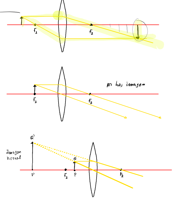
Graphical Methods for Thin Lenses
A very useful tool for corroborating or making sense of the calculations we perform are the graphical methods drawn below; such methods are analogous to those used with mirrors.

These methods provide different results depending on the object’s position in front of the lens.
Exercises:
- A divergent lens and a parallel beam of rays “open up” as they pass through it so that their projections converge to a point located 30[cm] from the center of the lens. If you want to use this lens to obtain a virtual image 1/2 the height of a certain object:
- Calculate where such an object must be placed.
- Make a ray diagram to describe the situation.
- An object 7[cm] high is placed 13[cm] to the left of a convergent lens with a focal length of 5[cm]. A second convergent lens with a focal length of 2[cm] is placed 30[cm] to the right of the first lens, sharing the same optical axis. Find the size and position of the image generated by the two combined lenses.